General tab on the EcDefect control's properties page
When the properties page opens it appears like that shown in the Figure below. Select the tab for the properties you are interested in viewing/editing. For Irregular Defect types two additional tabs appear: Model and Elements as shown in the Figure.
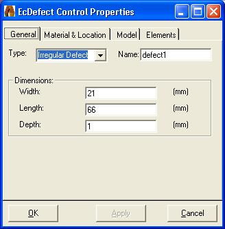
Use the General tab to set the EcDefect control's Type, Name and Dimensions. If the channel being modelled does not have a defect then the type should be set to Unflawed. Using this type of defect allows for lift-off studies, field studies and/or material properties studies.
General tab on the EcDefect control's properties page
If the channel being modelled has a defect, the EcDefect control provides physical model of defects. It represents every defect as a collection of volume cells with a constant conductivity. Cells completely inside the defect have the defect's conductivity (usually zero) and cells totally outside the defect's volume have the host's conductivity. If a cell is partially in the defect volume and partially outside the defect volume its conductivity is defined by using the volume fraction.
The EcDefect control knows how to model certain types of defects and will map the defect to the volumetric cells represented by the dyadic operator automatically. These types appear in the pull-down list:
Other types of defects have to be modelled by hand using the Irregular defect type. For more information about Irregular defect types see the Model and Elements tab sections.
For all the defect types, except Unflawed, use the Dimensions section to set the overall volume of the defect.
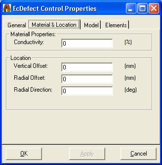
Use the Material & Location tab to set material properties and defect location
properties. A typical view of the Material & Location tab is shown in the
Figure below.
Material & Location tab on the EcDefect control's properties
page
The Conductivity is a percentage of the host's conductivity, which is usually zero. However, if the defect has corrosion products in it, it might be best modelled as a volume containing a region of 50% of the host's conductivity.
The Location properties allow you to offset the defect from the surface or the centre of the scan.
For Irregular Defect types the user must define the defect cell by cell similar to painting an icon. First determine the number of cells that will be used to define the defect. This choice is independent of the choice of dyadic operator size. The EcDefect control will map from the Irregular cell sub-division onto the one needed by the dyadic operator model. So you are free to choose a useful size. For example, in the following two Figures you can see that a size of 7 x 22 made a useful grid for designing the NDT defect.
You can use a template to help you generate the defect. For example, you might use the bore-hole template to generate a round hole then add a crack in the corner. You use the Elements tab to view/edit individual defect elements.
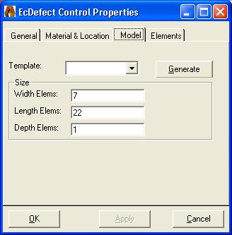
Model tab on the EcDefect control's properties page
The Figure below shows how you might design three separate defects in one defect volume. The cells shown in black are 0% of the host's conductivity, while those in white are 100% of the host's conductivity. If any of the cells had values in between, they would be shown in grey scale.
To edit the value of an individual cell, select it and change its percentage
value in the text box.
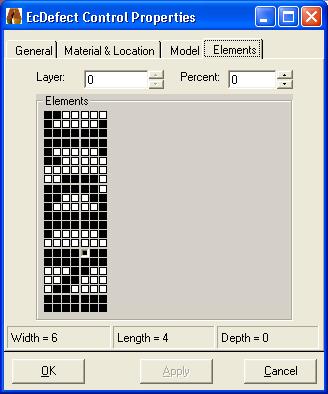
Elements tab on the EcDefect control's properties page