EcInspection control's View menu
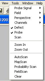
The Figure below shows the EcInspection control's View menu.
EcInspection control's View menu
The Probe Signal menu is used to control what filter is applied to the status bar display of the EcInspection control as the probe is moved around the display.
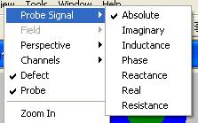
EcInspection control's Probe Signal menu
The field menu is enabled when modelled fields are present in the Inspection. Use the menus and commands here to choose and view the fields.
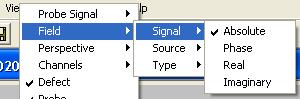
EcInspection control's Field menu
The Signal menu shown in the Figure above determines the filter applied to the field values as the mouse is moved around a field scan.
The Source menu is used to determine which Field Source is displayed in the field scan. The Figure below shows the Source menu. If a scattered field has not been modelled, the choice will not be available as shown in the example below.
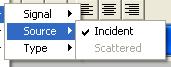
EcInspection control's Field::Source menu
The Type menu is used to determine which type of Field Type is displayed in a field scan. The Figure below shows the Type menu. You will be able to select only the type of field that has been modelled.
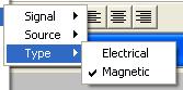
EcInspection control's Field::Type menu
The Perspective menu is used to determine the view presented by the EcInspection control. The choice of view perspectives are shown in the Figure below. For cylindrical work-pieces, the Top view is equivalent to an end view. The current view perspective is shown in the status line. Clicking on this panel in the status bar also provides you with the same menu of choices.
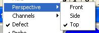
EcInspection control's Perspective menu
Use the Channels menu to determine which of the Inspections channel is 'in focus'; only this channel is visible in the EcInspection control. The channel currently in focus is ticked in the menu as shown in the Figure below. The channel name is also displayed in the status bar. Clicking on this panel will also bring up the Channels menu.
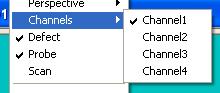
EcInspection control's Channels menu
The user can hide or show the defect, probe and scan objects in the EcInspection control by toggling these menu items.
Use the Zoom In or Zoom Out commands to zoom into or out of the view. Using this command either doubles or halves the view perspective. The current view scale is shown in the status line. Clicking on this panel allows you to enter the viewing scale directly.
The Autoscan command simulates the scan described in the Inspection. For example, if a raster scan has been modelled, an autoscan will drag the probe along the first primary scan, pick it up, move it to the beginning of the next primary scan (determined by the secondary scan) and drag the probe along this primary scan. At each scan point the probe's signal for all modelled channels will sent to all display devices.
The MapScan command performs the Autoscan discussed above, but instead of sending the probe signals to any display devices, the current Probe Signal filter is used to produce a grey-scale map. The maximum signal is shown in white, while the minimum signal is shown in black, while values in between are mapped linearly in between these colors. The two Figures below show MapScans for air-cored probes over a slot in a block and a through-wall borehole in a plate.
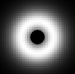
2 MapScans of a slot and a borehole defect
The Probabilty Scan command looks at probe signals at multiple points to estimate the probability that there is a defect at that point and what its width and length might be. This process is applied across the entire area of the scan and an overall probability is assigned for each point. The length and width is then drawn for points with more than 25% probability. With an overall red-scale applied. The Figures below show Probability Scans for the two defects shown above.
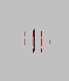
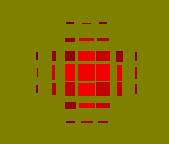
Probabilty scans of the 2 defects above - bright red is highest
probability
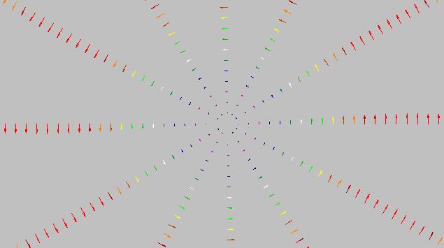
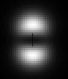
FieldScan of the Incident Electric field from an air-cored probe
Clears the EcInspection control and resets it to the default condition.