EcProbe control properties
As with all our EddyCentre controls, right clicking on the EcProbe control
at any time you can see the EcProbe control's hot-menu shown below.
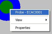
EcProbe controls hot-menu
Using this menu you can:
- View the name of the control
- Change the view
- Open the EcProbe control properties dialog box.
General tab
The EcProbe control properties dialog box allows you to change all aspects
of the probe; its name, its type, etc. A typical view of the properties dialog
box is shown below. For air-cored probes you will only see the general tab as
shown.
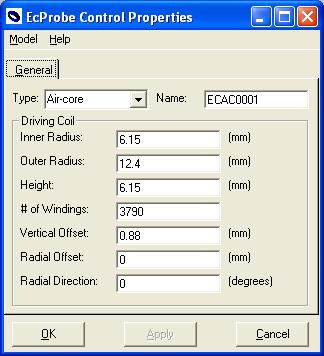
General tab on the EcProbe control properties window General
tab
The EddyCentre Probe control supports 5 types of eddy-current probes:
- Air-cored probe
- Pencil-cored probe
- Shielded core probe
- Cup-cored probe
- Differential probe
Name - Name of the control (must be non-blank)
Driving Coil parameters:
- Inner Radius - the inner radius of the driving coil (must be > 0), shown
as r1 in figure below.
- Outer Radius - the outer radius of the driving coil (must be > Inner
Radius), shown as r2 in figure below.
- Height - the height of the coil itself, not the entire probe (must be >
0), shown as h in figure below.
- Number of Windings - the number of complete turns in the coil, can have
a fractional part (must be > 0).
- Vertical Offset - the vertical offset of the coil from the bottom of the
probe; not to be confused with lift-off. Probes often have wear plates on
the bottom. (must be non-negative), shown as l in figure below
- Radial Offset - amount of radial offset the driving coil centreline has
from probe centreline (must be non-negative), there is no Radial Offset in
the figure below.
- Radial Direction - direction of radial offset.
Cross-section view of air-cored probe
Central Core tab
If you have selected any of the ferrite-cored types of probes you will see
additional tabs in the properties window. The Central Core tab shown in the
figure below allows you to change the parameters that control the ferrite cylinder
inserted in the centre of the driving coil.
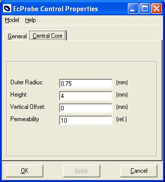
Central Core tab on the EcProbe control properties window
Central core parameters:
- Outer Radius - the radius of the central core (must be > 0), shown as
r1 in the figure below.
- Height - the height of the cylinder of ferrite (must be > 0), shown as
h1 in the figure below.
- Vertical Offset - offset of the core from the bottom of the probe (must
be non-negative). Don't confuse this with lift-off, some probes have a wear
plate under the driving coil, the value is zero in the figure.
- Permeability - The permeability of the ferrite itself (must be > 1).
Cross-section view of pencil-cored probe
Shield tab
For shield core and cup-cored probes you use the Shield tab to control the parameters
that define the shield. For shielded core probes the shield is a simple cylinder
of ferrite added outside the driving coil, as shown in the figure below. Cup-cored
probes have an additional disc of ferrite on top of the central core and shield
which forms one large circuit for the magnetic flux, as shown in the cross-sectional
view below.
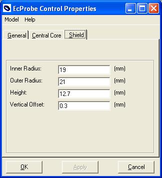
Shield tab on the EcProbe control's properties page
Shield parameters:
- Inner Radius - the inner radius of the shield (must be > driving coil
Outer Radius), shown as r2 in the figures below.
- Outer Radius - the outer radius of the shield (must be > Inner Radius),
shown as r3 in figures below.
- Height - the height of the shield (must be > 0), shown as h2 in the figures
below.
- Vertical Offset - the vertical offset of the shield from the bottom of the
probe (must be non-negative). Do not confuse this with lift-off, many probes
have a wear plate on the bottom, shown as zero in both figures.
NOTE: for cup-cored probes Height + Vertical Offset must be > than the driving
coil's Height + Vertical Offset
Cross-section view of shielded core and cup-core probes
Pickup Coil tab
If you have selected a differential probe type you will see the additional PickUp
Coils tab, shown in the Figure below. You view/edit the parameters on this page
to control define the 2 pick-up coils used in the probe. Differential probes
are not axi-symmetric, like all the other probes. The orientation of the pickup
coils relative to the scanning direction is significant. Using the Radial Direction
angle as described below controls this orientation.
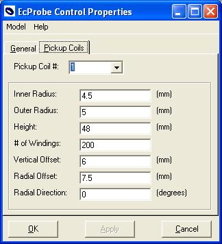
Pickup Coils tab on the EcProbe control properties window
Pickup Coil parameters:
- Pickup Coil # - selector for which pickup coil you are viewing/editing.
- Inner Radius - inner radius of the coil (must be > 0), shown as r1 and
r3 in the figure below.
- Outer Radius - outer radius of the coil (must be > Inner Radius), shown
as r2 and r4 in the figure below.
- Height - the height of the coil itself (must be > 0), shown as h1 and
h2 in figure below.
- Number of Windings - the number of complete turns in the coil, can have
a fractional part (must be > 0).
- Vertical Offset - the vertical offset of the coil from the bottom of the
probe; not to be confused with lift-off. Probes often have wear plates on
the bottom (must be non-negative).
- Radial Offset - amount of radial offset the pickup coil centreline has from
probe centreline (must be non-negative), shown as o1 and o2 in the figure
below.
Side View of a Differential Probe type
Radial Direction - direction of radial offset relative to the positive x-axis
(shown as a1 and a2 in the figure below - hence a1 = -a2 = 90 deg).
Top View of a Differential Probe type