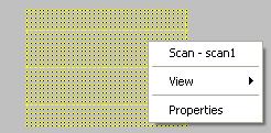
Top view of EcScan control's raster scan
The EddyCentre Scan control determines where the actual probe signals are modelled. Use the EcScan control to determine the extent and resolution of the scan for each channel. A typical view of the EcScan control is shown in the Figure below. As with all the EddyCentre controls, right clicking on the control brings up a hot-menu, which identifies the object and allows access to change the view or access to the objects properties page.
Top view of EcScan control's raster scan
The EcScan control draws a yellow dot for each scan point in the scan. You will find that the scan actually 'covers' the entire region it is drawn on. To right click on the work-piece region, you may have to hide the scan control first (this is the default behaviour of the EcInspection control).
If the probe and defect are symmetric, then the EcScan control will automatically expand to show the symmetric extent of the scan. For example, for the raster scan shown in the Figure above, only the upper right-hand quadrant was actually modelled. The remaining scan extent comes free through symmetry.
The EcScan control can represent several types of scan types. We have already
seen the raster scan. The Figure below shows a typical pivot scan, which can
be produced by commercial automated scanning equipment. Again, symmetry has
been used to extend the scan azimuthally, to cover the left-hand side of the
scan.
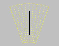
Top view of EcScan control's pivot scan
Another type of scan is the lift-off scan, which is shown in the Figure below. Typically, this type of scan is used on unflawed work-pieces. For lift-off scans, the default is front view and each scan point is shown as a dotted line, as probe position in the x-y plane does not change the signal.
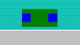
Front view of EcScan control's lift-off scan