EcModel control's property page for Simple Probe model type
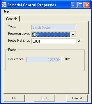
If the EcModel type is Simple Probe then the property page appears like that below.
EcModel control's property page for Simple Probe model type
The Type text box shows the type of the EcModel control, but it cannot be edited.
The approximation of L0 is controlled by the use of a
relative error term, the smaller this term the higher the precision of L0.
The Precision Level pull-down and the Probe Relative Error text box work in
unison to determine this relative error term. If you choose one of the 3 precision
levels: Low, Medium or High, the EcModel control will set the probe's relative
error term to 0.01%, 0.05% and 0.001% respectively. This basically says that
you want 2, 2.5 and 3 significant figures in Lo. You can set the relative error
yourself by typing directly into the text box, in this case the Precision level
will be set to Advanced.
If the simple probe has been modelled, the value of L0
will be displayed in the Inductance text box.
The properties page for the Channel type model is shown below.
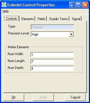
EcModel control's property page for channel model type
The precision level determines the accuracy that the model uses: the resolution of the sub-division of the defect volume and the relative error with which the field and individual dyadic terms are computed.
The defect volume needs to be subdivided into volumetric cells in order to model the channel. The volumetric sub-division is uniform; so all the volumetric cells are the same size. The model then calculates the dyadic operator that defines how the cells interact. The model solves a large linear system, Ax = y, for the dipoles, x, assumed constant in each cell. The matrix A is an n x n matrix, where n is the number of unknowns times three, because the fields have three components. The number of unknowns is just the number of cells in the defect volume. The vector y is the components of the incident field at the centre of each of the volumetric cells.
The sub-division of the defect volume must be of the same order of the skin-depth
of the channel. The skin-depth, k, is defined as:
k = sqrt(omega x conductivity x permeability),
The skin-depth is the wavelength of the field in the work-piece. Skin-depth
is an important parameter in eddy-current testing as the fields and currents
are contained in a 3 skin-depth volume about the probe. The EddyCentre model
involving the defect cell volumes involves a Taylor's expansion in k,
so the cell dimensions need to be small relative to this amount.
If the precision level is not set to Advanced, then the sub-division of the defect volume is done by the EcModel control. It uses the following formulas:
where di is the defect volume dimension in the ith co-ordinate direction (for cylindrical geometries, dx = dr, dy = r dtheta) and ceil(x) is the smallest integer greater or equal to x.
If the associated EcChannel control does not have a defect the Matrix elements
text boxes and the Elements tab will be disabled.
If the EcProbe control contained in the EcChannel control has a ferrite core
and/or shield the probe is much more complicated to model. This is because the
ferrite modifies the incident electric field and the magnetic field scattered
from the defect (if present). The ferrite is modelled in a similar way to the
defect in the Channel EcModel type. The ferritic core and shield (if present)
are sub-divided into volumetric cells. The dyadic operator is found that describes
how the cells interact with each other and then the linear system Ax = y can
be solved for the unknown magnetic dipole distribution x given the incident
electric field y.
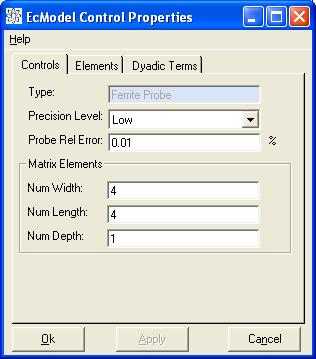
EcModel control's property page for Ferrite Probe model type
The elements and dyadic terms will also be needed if the probe's impedance signal is to be modelled.
Use the Elements tab, shown in the Figure below, to view/edit the way the
defect volume is sub-divided for Channel model types or to view/edit the way
the ferrite core and shield is sub-divided for Ferrite Probe model types. You
are provided with a view one layer at a time. The number of elements is determined
on the Controls tab.
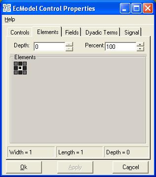
EcModel property page Elements tab
In both cases the percentage determines how much of the volumetric cell is defect/ferrite. For example, the Figure above shows how a 3 x 3 defect layer might appear when it is modelling a borehole. Notice that the centre volume is 100%, while those adjacent are only 85% and the corners are 58%.
If you want to change a cell's value, simply highlight it (like the centre one has been in the Figure) and then type in the Percent text box or use the Up/Down buttons to change that cell's value. You can change the layer you are looking at to view/edit elements for those layers.
Use the fields tab to control select which fields are to be modelled. The Figure
below shows a typical view of the Fields tab on the EcModel control's property
page. You can choose which regions, source and type of fields by selecting the
field and pressing the Properties button.
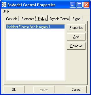
Fields tab on the EcModel control's property page
For Channel EcModel types with defects present, the incident electric field in the defect region must be computed. The EcModel control will automatically add this field to the list and you will not be able to remove it. You can increase the resolution of this field, however, the EcModel control will ensure that the field resolution and extent are sufficient for the modelling requirements.
A typical view of the Field's Property page is shown below. In this view the
General tab has been selected.
Use the General tab on the Field's property page to set the field's parameters.
The parameters are:
The General tab also provides a tree view of the field: showing its parameterisation
as well as the field values themselves (if they have been modelled).
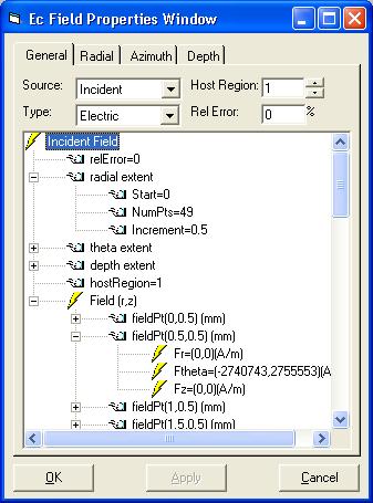
Field Properties page
The Radial, Azimuth and Depth tabs are all similar. A view of the Radial tab
is shown in the Figure below. Incident fields are always radially symmetric
and only the radial and depth component need be selected. Scattered fields cannot
be assumed to be radially symmetric. For this type of field the Radial and Azimuth
tabs change to Primary and Secondary for the raster grid defining the points
where the field is to be computed.
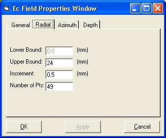
Radial tab on the Field Properties page
Use the text boxes to define the resolution and extent of the points where the field is to be modelled.
The Dyadic Terms tab provides a tree view of the dyadic elements used by the
EcModeller to describe the interaction between defect or ferrite volumetric
elements. The only user parameter that can be adjusted on this tab is the relative
error term. This term is associated with the Precision Level on the Controls
tab, but you can override the relative error term here. Overriding this term
will change the Precision Level to Advanced. For more information about the
dyadic terms please see our EcModeller's Analyst's Guide.
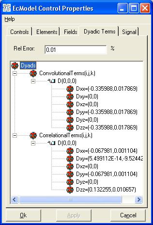
Dyadic Terms tab on the Field Properties page
The Signal tab provides information only. You can view the signal modelled
by the EcModeller as well as the balance point and lift-off signal information.
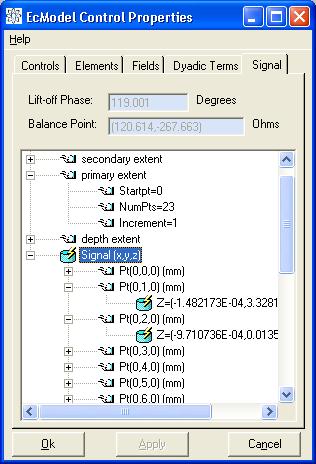
Signal tab on the Field Properties page